From G503Wiki
Back to the Ford GPW Judging Standard Index Page!
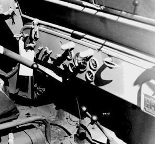
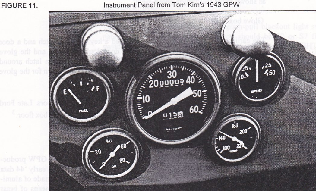
Instrument panel of GPW from approx May 1943 production
Back to the Ford GPW Judging Standard Index Page!
Instrument panel of GPW from approx May 1943 production
8.1 Light switches
There are three light switches which may be found on the dashboard.
Blackout Driving Light switch: Vehicles which included a blackout driving light and did not have a rotary type blackout light switch had a push-pull type switch installed at far left of the dashboard. Switches before mid 42 should have an OD painted cast metal knob, those after are plastic. The embossed legend B.O. DRIVE should be filled in white paint.
Blackout Light switch: This was the main light control switch, located on the dashboard between the blackout driving light switch (if any) and the choke control. Most GPWs used a push-pull type switch with a locking detent to prevent inadvertent activation of the service lights. Around June 1944* the push-pull light switch was replaced in new production with a rotary type switch. The rotary switch incorporated a plastic escutcheon plate with a legend describing the various switch positions. Vehicles incorporating the rotary switch should delete the blackout drive switch as its function is subsumed by the rotary blackout light switch.
The knob and locking collar on the push-pull blackout light switch should be painted OD. The lockout push-button should be S2 or S7 finished and the switch shaft should be S7 finished. The knob is marked LIGHTS in white.
Instrument light switch: This switch operates the small lamps above the instrument cluster and is located to the right of the steering column. This is a pushpull type switch, as described under Blackout Driving Light switch except for the knob, which is marked PANEL LIGHTS.
* Per AAW II, Pg. 252
Updates to this info below this line
enter your info here...
Note: From what I have seen the dash knockout for the primer pump only came on factory GPW Ford made bodies on the 4th GPW contract. This ran from about mid March 43 till in the fall of 43 mostly Sept. at which time each plant would have switched over to using the ACM type 1 Willys body. Tom Wolboldt
Note: GPW 213313, matching, orig. plates DOD 7-26-44 with CB Body 81674, p-p- switch . Has M2 Decontaminator holes factory behind the passenger seat. Owner:-Lars-Uwe Rudek Germany
8.2 Choke & throttle
The correct GPW choke and throttle cable incorporated metal knobs, painted OD with raised markings picked up in white paint. The cable housings consisted of zinc or cadmium plated spring-steel wire wrapped to form a conduit(Belden cable). The conduit should remain unpainted.
Updates to this info below this line
8.3 Ignition switch
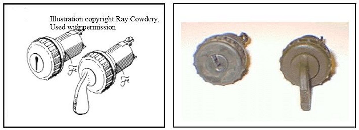
All GPWs used a unique ignition switch which is easily recognized by the raised ridges on the bezel (retaining ring).From start of production, ignition switches were key operated, but along with most military vehicles, this was changed to keyless around 1/43. The entire exposed portion of the ignition switch is painted OD. Note: key and keyless ignition switches appear identical except for the barrel and bezel. Keyless switches are easily converted to key type and vice-versa, however original keyed switches have a smaller bezel hole as shown in the illustration above-right*.
Glove box
The earliest production vehicles incorporated a key operated latch and a door spring that engaged slots in the glove box door doubler (hinge) and the glove box floor. The locking latch was replaced with the push-button latch around May-June 1942. Late production vehicles eliminated the provision for the glove box door spring in the door hinge and glove box floor.**
Glove Box floors: Early Ford built bodies had flat glove box floors. Late Ford production and ACM bodies had two reinforcing beads in the glove box floor.***
* Ignition switch photo and information supplied by Ron Fitzpatrick ** Per T.Sudds *** 2 4/43 bodies (ford mfg) had this reinforcing bead. Believe it was introduced by Ford sometime between 8/42 and 4/43 -BK.
Updates to this info below this line
8.4 Data Plates
Several different styles of nomenclature plates were used during GPW production. Early GPW data plates were made of brass, late 42 through early 44 data plates were made of plated steel and 44-45 GPWs used plates made of aluminum. The data plates are attached to the glove box door by means of brass plated steel rivets.
Data plates were changed to show Ordinance Dept. as the servicing organization on 12/3/1942. Vehicles built before this date had the Quartermaster Corps (QMC) as the servicing organization.*
* There were about six different variations of serial number plate used during production. These should be documented and included here in future revisions.
Updates to this info below this line
Various styles of Data Plates can be seen on http://rdrnl.home.xs4all.nl/4UWPFordGPW.html
8.5 Instruments
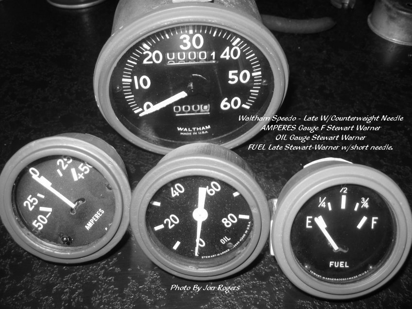
Stewart Warner was the primary supplier of gauges for Ford GPWs. Most Stewart Warner gauges are marked with the manufacturers name and model number at the bottom of the dial face.
Early GPWs used Stewart Warner paint can lid removable bezel type gauges. These appear to have been changed to the standard type sometime around 3/42.
Updates to this info below this line
8.5.1 Speedometer
GPWs came equipped with 60 Mile per hour speedometers. The pointer and the 0, 10, 20 and 20 MPH marks are coated with luminescent paint.
Most GPW Speedometers were made by Waltham but other makes may have been used as well. Later models included a counterbalanced pointer, while the earlier vehicles used two different variations of triangular pointer.
Updates to this info below this line
The pointer, 10 mph and 20 mph marks are coated with luminescent paint. Most Gpw speedometers were made by Stewart-Warner but King Seeley and Waltham (from approx. Feb 43) were also used. - Sean Elliott
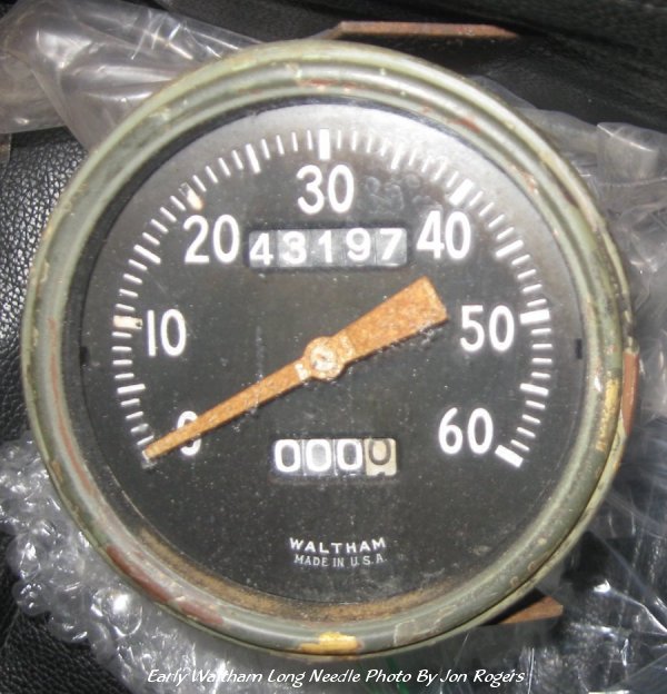 Early Waltham Long needle
 Stewart-
Warner Gauges and Waltham - Photo By Jon Rogers
Stewart-
Warner Gauges and Waltham - Photo By Jon Rogers
8.5.2 Oil pressure
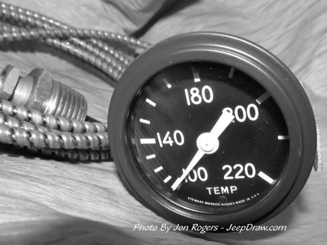
8.5.3 Temperature
Stewart-Warner Temperature gauges used a flattened band wrapping, to protect the temperature gauge tube. This differs from the spiral wire shield used on Autolite units.
Stewart-Warner temperature gauge needles are blunt-ended as compared to the pointy Autolite gauge needles. Early Stewart Warner needles (thru at least 4/43) extended past the top of the gauge graduations. Later needles were shorter and rounded at the end.
Updates to this info below this line
 Photo
Supplied By Jon Rogers
Photo
Supplied By Jon Rogers
8.5.4 Ammeter
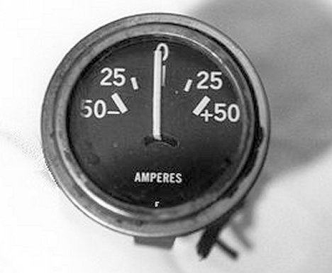 Early S.W.
Ammeter, with F
Early S.W.
Ammeter, with F
Stewart warner Ammeter gauge needles,like the temperature gauge needles, are blunt-ended as compared to the pointy Autolite gauge needles. Early Stewart Warner needles (thru at least 4/43) extended past the top of the gauge graduations. Later needles were shorter and rounded at the end.
Updates to this info below this line
The changeover from the "F" marked Amp gauge to the Stewart-Warner marked Ammeter Gauge appears to be about June 1944 - Jon Rogers
8.5.5 Fuel
This Web Page Created with PageBreeze Free HTML Editor