g503.com GPW Judging Standard
WIKI-ENGINE
Back to the Ford GPW
Judging Standard Index Page!
3.0.1 Engine block
3.0.1 Engine block
The engine block is finished in a medium gray gloss enamel.
Two colors of gray were used during GPW production. The earlier
color is a cold slate-gray while the later color is lighter and warmer.The date
of the color change is not known at this time.
Cast markings: GPW 6015 in raised letters on lower-right side of
block, with a script f above.
Early engines had a
casting date code located on the lower rear corner of the right side of the
block. This code included a single letter representing the month (i.e. A =
January) and the numeric representation of the
day. An additional digit may have represented the mold pattern number.
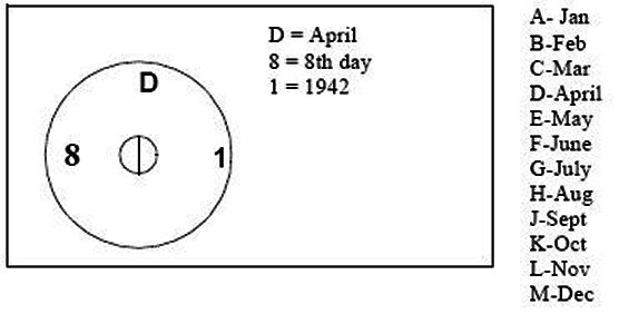
Around August, 1943, engine casting dates were relocated on the
block. These date codes were located below the distributor and started with a
letter representing the month followed by the day and the last digit of the
year. For example H3311 was cast on August 3, 1943. The final two digits
may indicate the mold or line number.
The serial number pad, located behind the oil filter is stamped
with the engine serial number. The engines were stamped with their serial number
when the blocks were machined, and the chassis were stamped with the engines
serial number at the time the engine was mated to the frame. As a result,
occasionally GPWs would roll off the assembly lines with a serial number that
would appear to belong to a much older vehicle.
Around 12/42, the block casting or machining process was
changed, resulting in a change to the serial number pad. At this point, the pad
was no longer machined uniformly smooth from front to rear, but incorporated a
step at the very rear of the pad.
Engines numbered 232051 through 243405 use studs NOT bolts to
retain the valve covers. Use of bolts in these blocks will crack the cylinder
wall bosses. Also, all spare engines with casting dates of K-10-4 to L-29-4 were
changed to studs.*
The engine serial number should match chassis and data plate
numbers. Non-matching serial numbers will result in a significant deduction of
judging points.
* Per J.Gilmore archival research (!FoMoCo 12/44)
Updates to this info below this line
3.0.2 Engine front mounting plate
3.0.2 Engine front mounting plate
The engine front mounting plate was changed sometime in early 1943* with the
addition of a reinforcing plate on the generator side. This reinforcement was
attached with ***three (3) rivets near the timing chain cover.
*Ordinance Dept. report described in AAW VII states that change was made
1/16/43.
Updates to this info below this line
***Looking at several Front Plates, I think the CORRECT number of rivets for the
reinforced LATE-style is FOUR, not the THREE as shown in the printed version of
the Judging Standard above.
Chuck Lutz
3.0.3 Valve cover and crankcase ventilation
3.0.3 Valve cover and crankcase ventilation
The early road-draft crankcase vent system was used from start of production
thru February, 1943. After this, positive crankcase ventilation was introduced,
which resulted in changes to the oil filler tube, carburetor to air cleaner
crossover tube, intake manifold and the addition of a PCV valve and plumbing.
Updates to this info below this line
3.0.4 Cylinder head
3.0.4 Cylinder head
Cylinder head markings include script f and 6050 near oil
filter bracket.
The cylinder head is attached with 9 f Head bolts and 6 studs. The
studs have a visible dome end and are painted along with the block. The head
stud nuts, are heavy dimension and are S7 finished.
The center rear stud is longer then the rest, to accommodate the cylinder
head to firewall ground strap. A second nut, along with two flat washers and a
lock washer retain the cylinder head side of the strap.
The thermostat housing is marked GPW 8250 with a script f
Updates to this info below this line
The attaching of the cylinder head was all studs after
GPW 242992 - Jon Rogers
3.0.5 Oil pan and oil filler
3.0.5 Oil pan and oil filler
Vehicles produced before a certain date in 1942 included an early style oil
pan which used a cast drain boss, attached to the pan with three rivets and
sealed with solder*. The oil pan is fastened to the engine block with recessed
hex head integral-lockwasher bolts. The crankshaft pulley shield is fastened to
the timing chain cover with four recessed hex head lockwasher bolts that also
hold the front of the oil pan. Spacer rings are used between the shield and the
pan to prevent interference. The threaded ends of the bolts should not extend
too far past the timing cover flange. The pulley shield is properly marked with
a script f.
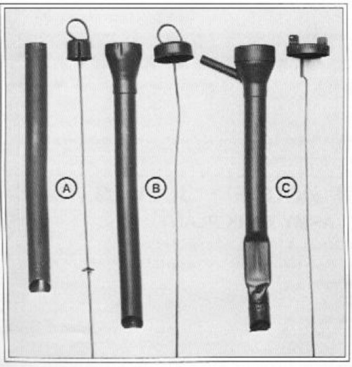
Three styles of oil filler tube and dipstick were used during GPW production:
A) The Very Early style (PN GPW-6763A) with narrow cap was used from start of
production thru March 42. B) The Early style (GPW-6763B) with friction-fit
funnel top was used from April 42 thru Dec 42. C) The late style (GPW-6763C)
with crankcase vent and bayonet cap was introduced Feb. 8th 1943 and was used
thru the end of production. **
The oil pump is marked GPW 6604 with a script f
* Have been unable to find any reference to change in oil pan. Date should
be determined based on documentation or observation. ** Changeover
date courtesy Jim Gilmore based on Ford archival research.
Updates to this info below this line
Part number for early style dipstick(B) should be GPW-6766B.(from NOS
dipstick with Ford tag attached) -Todd Haley
3.0.6 Manifolds
3.0.6 Manifolds
Markings: Exhaust GPW 9430 f , intake GPW 9425
f
PCV was introduced in February 1943* at which time the intake manifold was
drilled and tapped for vent lines. Before February 1943 the intake manifold was
not drilled and no bosses were present.
* Willys-Ford teardown report AAW#2, p213 states that Nov42 GPW did not
have tapped manifold.
Updates to this info below this line
3.0.7 Carburetor
3.0.7 Carburetor
The correct GPW carburetor is a Carter model 539S also known as type W-O. The
carburetor bowl, cover and horn are natural finished cast zinc (not gold).
The cast iron carburetor base is not drilled and tapped for a pipe plug as
are the later civilian carburetor bases. The base is finished with a black
chemical treatment similar to S2, it is dead flat with a white or gray tinge.The
throttle shaft lever, throttle arm, rod, choke link, choke lever and all
hardware are cad plated. The metering control rod is retained at the throttle
arm with a bayonet-type washer and spring which is usually missing or replaced
with an incorrect substitute. Most carb parts are marked with a Carter C logo
and the Carter part number.
The carburetor is mounted to the intake manifold with two 3/8 hex jam (thin)
nuts and split lockwashers, all S2 finished.
The carburetor linkage is painted gray with the exception of the return
spring which is S2 finished.
Updates to this info below this line
3.0.8 Oil filter and bracket
3.0.8 Oil filter and bracket
For most of production, the standard GPW oil filter was a purolator cartridge
type. Certain units may have utilized a Fram filter assembly after mid 1943.
The Purolator filter is identifiable by its dome shaped cover, marked
COVER ASSEMBLY 25791 PUROLATOR PRODUCTS INC MILITARY STANDARD
FILTER There are three decals on the filter assembly, a cover decal
describing servicing procedures, a body decal with a script f and the
part number GPW 18660 and one marked PUROLATOR PRODUCTS INC
CASE ASSEMBLY-26708 USE JUNIOR ELEMENT. The decal background is properly
a deep red color as compared to the incorrect orange decals commonly available
today. The oil filter body is stamped INLET in 1/4 block letters in
silver paint above the inlet port. The body, cover and cover bolt of the
Purolator filter are painted an eggshell finish black enamel. Oil filter bands
are made of 1/8x7/8 steel, slotted mounting holes have rounded ends. Bands,
screws and square nuts are painted black.
Flex oil lines are lacquered cotton braid cover (not rubber).
The oil filter bracket is painted gray engine color. The filter assembly is
attached to the oil filter bracket with S7 or S2* finished bolt, lock washer and
flat washer.
* Both S7 and S2 hardware appear in factory photographs.
Updates to this info below this line
Note figure 2(page 11) and figure 3(page12) of the judging guide show a FRAM
oil filter.
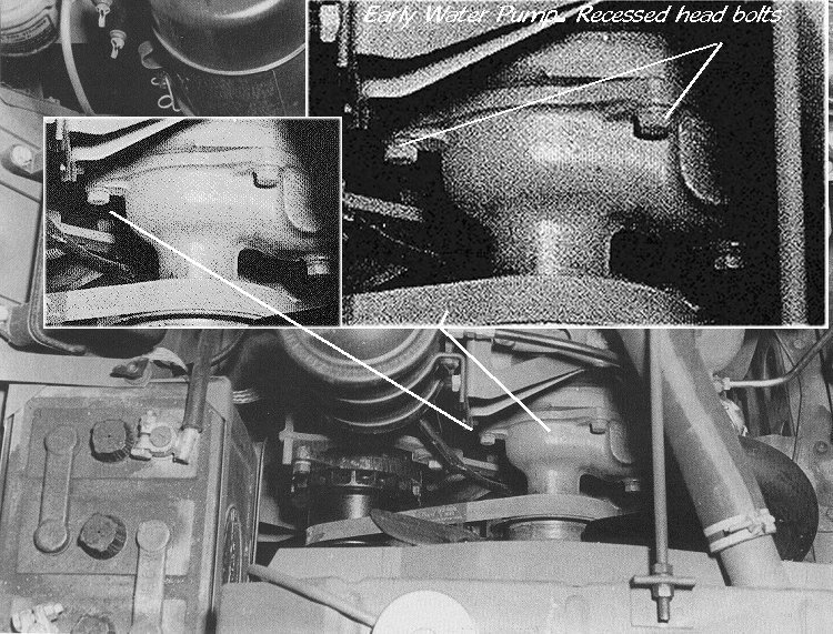
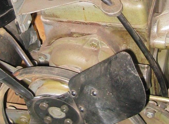
3.0.9 Water pump, Fan & fan belt
3.0.9 Water pump, Fan & fan belt
The fan is finished in semi-gloss black enamel and is attached to the
waterpump pulley with four S2 hex screws and split lockwashers. The water pump
is marked with a script f
Various types of Ford marked fan belts were used including one with the part
number GPW-8620 & S-2673 embossed on the belt in raised letters as well as
GPW-8620-A2 or GPW-8620-3 stenciled on the belt.
Updates to this info below this line
On later Water pumps, recessed hex head bolts were used. NOS Ford engine
photo below.

This Web Page Created with PageBreeze Free HTML
Editor