Master (and Wheel) Cylinder Servicing


� Repair kits are
available and sometimes the m/c and w/c’s
can be reclaimed by re-sleeving or honing and fitting these kits
.
� Oversize cups are
not available, as they once used to be.
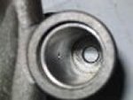
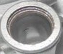
� Honing is not meant
to remove much material at all just clean up the bore which I would use
fine steel wool on first .
�
If there is any
pitting or indentations remaining in the bore caused by corrosion (or
whatever) the cylinder is not re-useable without re-sleeving.
�Fit up overhauled cylinders with special purpose
rubber grease (no mineral product allowed).
�
Keep in mind the
weakest link will fail and when that is repaired the next weakest will
fail.
� RECOMMENDATION is
all or nothing.
�
Brakes are one area
to do best the first time and save bucks down the line.
� Shop labour costs
in repairing will be higher than buying all new stuff and doing it
yourself.
� Sleeving is a great
(one time expensive) option to keep original and get long, long
life.
Steel Brake Lines
� These are made up of special steel tube made for
brake lines, double flared at all extremities. They should
not be made from copper or single flared. In some cases stainless
steel lines are used when salted roads and corrosion are
issues.
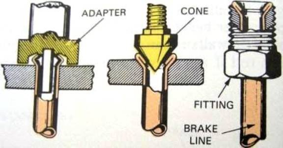
Double
Flared Steel Brake Tube
� With the right
flaring tool you can do it yourself with some practice .
�
Some little “ S ” bends are a little harder than
straight lines as we know!
�
Bending
should be done with special benders and
in some cases inside coiled springs meant for that purpose .
� Without
you will kink and ruin the tube, so
don’t try!
�
All lines
should be fixed with original type
clamping (or similar) in all original positions. Fatigue and
failure if not done properly .
Flexible Brake Lines
�
Flexible lines have
a use by date and NOS should be avoided.
�
When hand bent or
twisted if there is evidence of fatigue or perishing they should be
discarded and NEW stock ones fitted
�
Old hoses may show
up as a softer, spongy brake pedal .
� All original style
clips and attachments must be in place .
�
Appropriate tools
and techniques should be used when removing and replacing parts
Brake
Drums
�
Original brake
drums have a slot for feeler gauge measurement on adjustment with wheels
off.
�
This facility is
not too effective with badly worn or machined drums.
�
New stock drums
sometimes don’t have these
slots (see section on
adjustment)
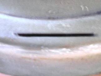
Feeler slot
�
Are hub mounted
using the wheel mounting studs swaged so the hub and drumjpg become one
part.
�
The drums can be
machined through various O/S to manufacturer’s limits and then replaced.
�
Drums should be
machined the same dimensions in a minimum of pairs preferably all four.
The drums and mounting studs (which are the wheel studs as well) are
serviceable.
�
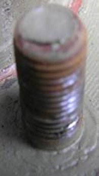
The drums which
become worn beyond limits, oval and bell shaped in service if outside
specification limits need to be replaced . This requires separation of the swaged (swedged)
components .
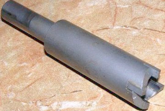
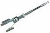
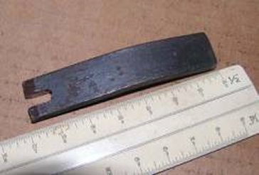
Swage Remover
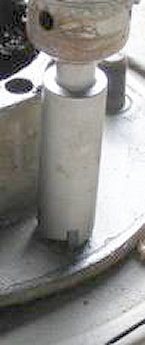
 Full Swage
Removal
Partial Swage
�
There are some
rough and ready ways to remove studs but I recommend you use a tool, like
this one from Bryce of “run
forest run” in a low geared
slow running drill, to relieve the effects of swaging. This will
allow you to press out the old stud more easily and safely. If you insist
on using a hammer (persuader) it will be easier and less dangerous if the
burring or swage is removed.
�
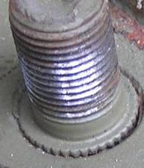
New drums and studs
should be fitted on perfectly clean flat surfaces between hub and drum and
re-swaged when installed .
�
This fitting should
be done with a press (support mounted under the wheel stud/s head/s
suggest a piece of 4” x
4” hardwood just short of the
drum dia and moving to suit) and a short piece of pipe which fits neatly
over the stud thread and just longer than the thread when fully home. Deep
socket?
�
Bushy style with a
persuader (BFH) is not recommended but some will insist.
�
Either way is
critical and if incorrectly implemented may require a complete re-do or
new drums to be skimmed to round!
Full Swage
Removal
Partial Swage
�
There are some
rough and ready ways to remove studs but I recommend you use a tool, like
this one from Bryce of “run
forest run” in a low geared
slow running drill, to relieve the effects of swaging. This will
allow you to press out the old stud more easily and safely. If you insist
on using a hammer (persuader) it will be easier and less dangerous if the
burring or swage is removed.
�
New drums and studs
should be fitted on perfectly clean flat surfaces between hub and drum and
re-swaged when installed .
�
This fitting should
be done with a press (support mounted under the wheel stud/s head/s
suggest a piece of 4” x
4” hardwood just short of the
drum dia and moving to suit) and a short piece of pipe which fits neatly
over the stud thread and just longer than the thread when fully home. Deep
socket?
�
Bushy style with a
persuader (BFH) is not recommended but some will insist.
�
Either way is
critical and if incorrectly implemented may require a complete re-do or
new drums to be skimmed to round!
Brake Linings
�
Linings can be
bonded or riveted, standard or oversize. There are two shoes leading (or front)
which is the longest and trailing (or rear) which is the shortest.
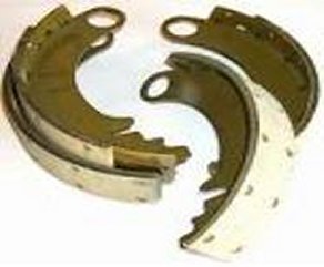
Short and long shoe
linings
� If the brake drums
have been machined, oversize linings need to be fitted and the shoes with
new O/S linings should be cam ground to suit the drum by your preferred
brake specialist. Standard linings = poor brakes if used
with o/s drums.
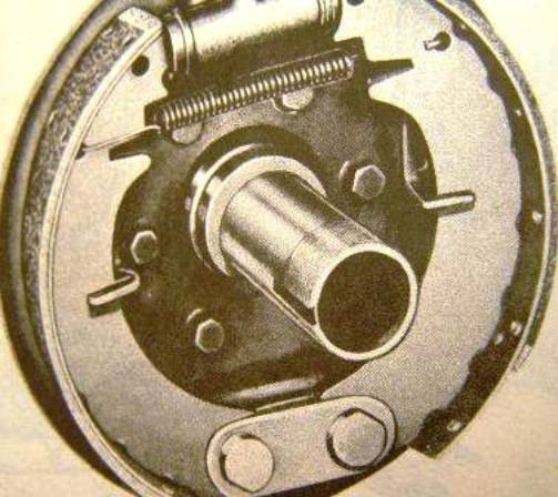
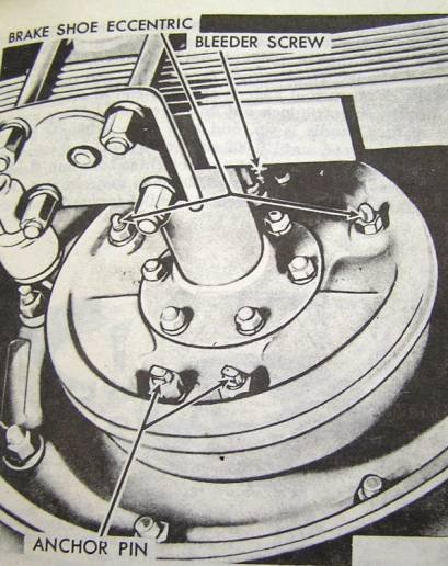
Backing Plate, Anchors,
Adjusters and Wheel Cylinders
�
Backing plates
require no service and unless mud and contaminants have fouled inside the
drum they should last the life of the vehicle and more.
�
There are two “U” guide slots riveted to each plate in which
the shoes are kept in line, rest and move. These should be free from
burrs, evident damage and wear signs.
�
Should be greased
with a lithium based product meant for that purpose e.g. “Lubeguard” which does not collect brake dust.
�
Anchors/major
eccentric adjusters are located at the bottom of and hold each shoe to the
backing plate.
� It is a good idea
to disassemble, clean and grease as above
�
Each shoe when
mounted correctly on the adjuster has the ability to move in and out and
up and down so as to adjust symmetrically to the drum ID.
 �
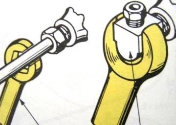
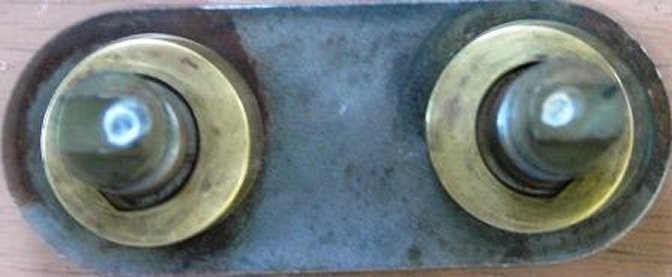
On the outside of
the backing plate the anchor pin adjusters have two indentations these
need to be as close together as possible on refitting and before adjusting
(See section on adjustment)
�
On the outside of
the backing plate the anchor pin adjusters have two indentations these
need to be as close together as possible on refitting and before adjusting
(See section on adjustment)

Anchor eccentric adjusters
�
Near the top of the
backing plate there are two eccentric adjusters for minor brake adjustment
(See section on adjustment)
�
Again these can be
disassembled cleaned and greased as mentioned above.
�
A brake return
spring connects both brake shoes and holds these in place mating against
the w/c piston receiving slots.
�
There are two (2)
diameter wheel cylinders and the larger 25mm (1 ”) is always fitted to the front axle as more
braking force is needed there because of weight transfer.
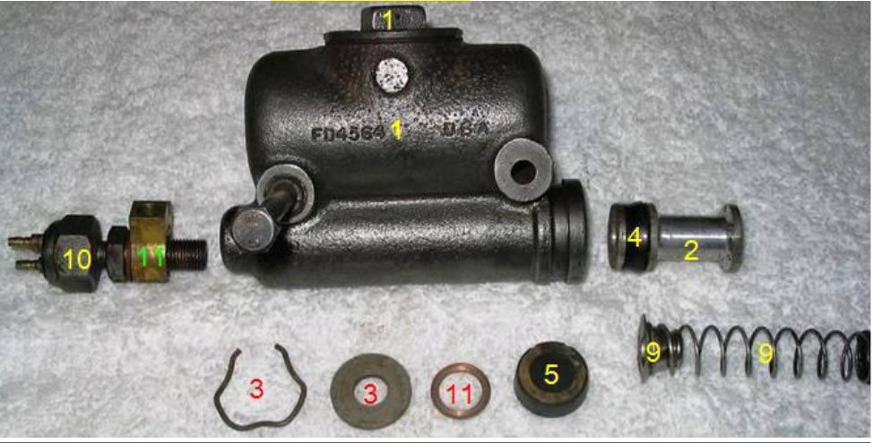
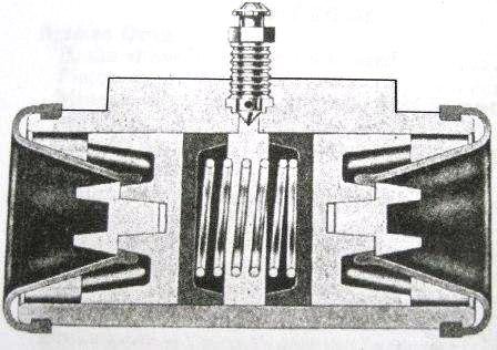 � The w/c contains a
light spring keeping two w/c rubbers and pistons apart.
� The flat rubber
surface fits against the flat piston surface
� Each w/c contains a
bleed screw which most folk like to over tighten. Suggest just
nip them up, light tension put on the rubber dust cap and seal around the
thread with a thick paint. Next guy to touch, then won ’t snap them off. Curses!
�
There are
aftermarket bleeders available with a one way check valve recommended by
some to help with bleeding, especially when unassisted.
Adjustment of Jeep Brakes (hydraulic)
� The w/c contains a
light spring keeping two w/c rubbers and pistons apart.
� The flat rubber
surface fits against the flat piston surface
� Each w/c contains a
bleed screw which most folk like to over tighten. Suggest just
nip them up, light tension put on the rubber dust cap and seal around the
thread with a thick paint. Next guy to touch, then won ’t snap them off. Curses!
�
There are
aftermarket bleeders available with a one way check valve recommended by
some to help with bleeding, especially when unassisted.
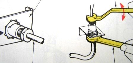
Adjustment of Jeep Brakes (hydraulic)
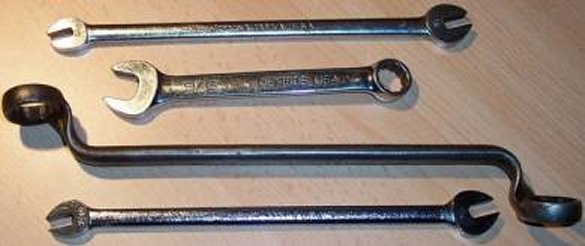
 Derek’s Tools & Someone’s Improvising
Note Derek’s modified ring spanner (box
wrench)
IMPORTANT:
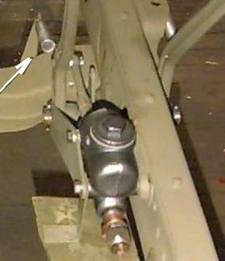
Before any
adjustment the foot pedal free play must be correct and the pedal return
spring in place as explained in the section on m/c
The brakes must be
normalized and not HOT.
Wheels must be off
the ground preferably on stands, in neutral, handbrake off and not
dragging.
Check shoes are not
dragging.
There are two types
of adjustment:
Minor for normal
in-service adjustment
Method: Everything
done as listed previously in IMPORTANT
Derek’s Tools & Someone’s Improvising
Note Derek’s modified ring spanner (box
wrench)
IMPORTANT:
Before any
adjustment the foot pedal free play must be correct and the pedal return
spring in place as explained in the section on m/c
The brakes must be
normalized and not HOT.
Wheels must be off
the ground preferably on stands, in neutral, handbrake off and not
dragging.
Check shoes are not
dragging.
There are two types
of adjustment:
Minor for normal
in-service adjustment
Method: Everything
done as listed previously in IMPORTANT
�
Lightly loosen the forward
located (leading) brake shoe eccentric lock nut with a ring spanner (box
wrench) and leave it in place so that you can retighten in one (1)
go. We
are talking of the top adjuster!
�
There is a special
tool (Snap On) 3/16” or
equivalent metric OE wrench (my kit does not go down that far) and at
worse a 100mm (4”) shifter or
adjustable and no bigger will do the job.
�
“If” the top adjuster has a dimple and it is away
from the wheel, the cam is off
�
The adjuster should
not feel real tight, if it does loosen the lock nut further (slightly) and
do not get a bigger (more leverage) type tool 3-4” is enough.
�
Usually you are not
turning too much but should the thread tend to tighten the locknut, loosen
a little more.
�
The cam is
symmetrical so you can turn either way but it is best to get used to a
certain method e.g. out toward the wheel for the front (leading) and back
toward the wheel at the rear (trailing) then when you adjust next time you
turn the same way and get immediate results.
�
Turn the adjuster
until the shoe just locks the drum, then in the opposite direction to
loosen until the wheel just turns freely.
�
There is a very
small difference between just locked and turning freely.
�
With the wrench held in place on the adjuster,
retighten the adjuster lock nut. That is why we left the ring spanner in
place!
� Systematically do
all wheels should take < � hour or maybe an
hour maximum with a
couple of stubbies (beers).
Major normally done after dismantling and some
serious type maintenance with the vehicle on stands and wheels
off.
 Adjusters in cam off position
Turn both down at
the dimple to start your major adjustment
Adjusters in cam off position
Turn both down at
the dimple to start your major adjustment
�
This adjustment
realigns shoes with the drums after re-line, drum skimming, new drums and
the like.
�
OEM drums are
slotted to fit feeler gauges to measure clearances; some aftermarket drums
do not have these slots.
�
One could drill a
small hole (1/16”) depth
limited in each drum so that wire gauges could do the job, being extremely
careful not to drill into the finish drum to shoe bore.
�
All the IMPORTANT
things done?
�
If the drums are worn and linings are scored go
straight to the section NO SLOT METHOD
�
You can do your
minor adjustment as related above and the top major reading .008” should be pretty right but
recheck anyway.
�
Major Adjustment is
accomplished by turning the anchor pin dots toward each other and then
down until the shoes are set to the proper clearance using a feeler
gauge
�
The recommended
shoe setting is .008” at the
toe (upper end) and .005 clearance at the heel (lower end) each 25mm
(1”) in from the lining
extremity
�
Loosen the anchor
lock nut on the forward primary shoe (not too much) leaving the wrench
attached (notice how Derek has a permanently modified and shaped a wrench
to fit above).
�
With the feeler
slot or drill hole 25mm (1”)
in from the end of the toe (top) of the leading shoe check and adjust for
.008” by turning the anchor
dot downward
�
Move the drum so as
to have the slot 25mm (1”)
from the bottom (heel) of the same shoe, check and adjust to
.005.
�
Tighten the locknut not allowing the anchor bolt to
move while doing so otherwise the adjustment will alter
�
Check for drag and
if dragging do again
�
Mark locknut with
chalk when done
�
Then do each other
shoe on the vehicle the same way remembering that the trailing shoes are
shorter so the position of the feeler will be different
NO SLOT
METHOD
� I will offer
another method not requiring the slots or drill holes lifted from a WWII
publication related to light Chevy Blitz trucks (thanks to Jimmy Sewell,
an old buddy from TAFE days) which is simple, quick and easy. Presumably it
will work on Ford GPW’s with
no ill effects from cross pollination, envisaged!
All the IMPORTANT
things done?
Do your minor
adjustment as related above
�
Apply a force of
25-35# to the brake pedal. This force must be consistent and maintained
through out the entire adjustment.
�
This is not much
force; place a small piece of wood in between the pedal shaft in the
engine compartment and the firewall holding the pedal down slightly and
consistently just past free play.
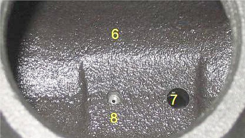
�
This force moves
the m/c piston enough to close the compensating or equalising port but not
move the wheels cylinder pistons!
�
All bottom anchor
pin dimples should be as close as they can be together (adjacent to one
another)
�
When their locknuts
are loosened we use the system of leaving the ring spanner (box wrench) on
the anchor lock nut as we did above
�
Adjust each of the
8 anchor pins (in turn) moving the dimple downward with no more than
3” long wrench until the shoe
just touches, indicated by very slight interference when turning the drum,
back off a fraction
�
Tighten the anchor
pin lock nut as you complete each one ensuring the anchor pin does not
move and mark as done with chalk
�
Remove the pressure
from the brake pedal and make sure all the brake drums turn with absolute
minimal to no dragging
�
If the shoes drag
you need to do it again. Be more careful this time as 4 stubbies
(beers) affects concentration!
�
Road test when
under .05 in an area with little traffic. After a little bedding in try a
few repeated hard applications.
�
Pulling up in a
straight line ?? you’re
a winner!
Sketches and
diagrams are courtesy of the odd g503.com post, Bendix, Snap On and
TM’s.
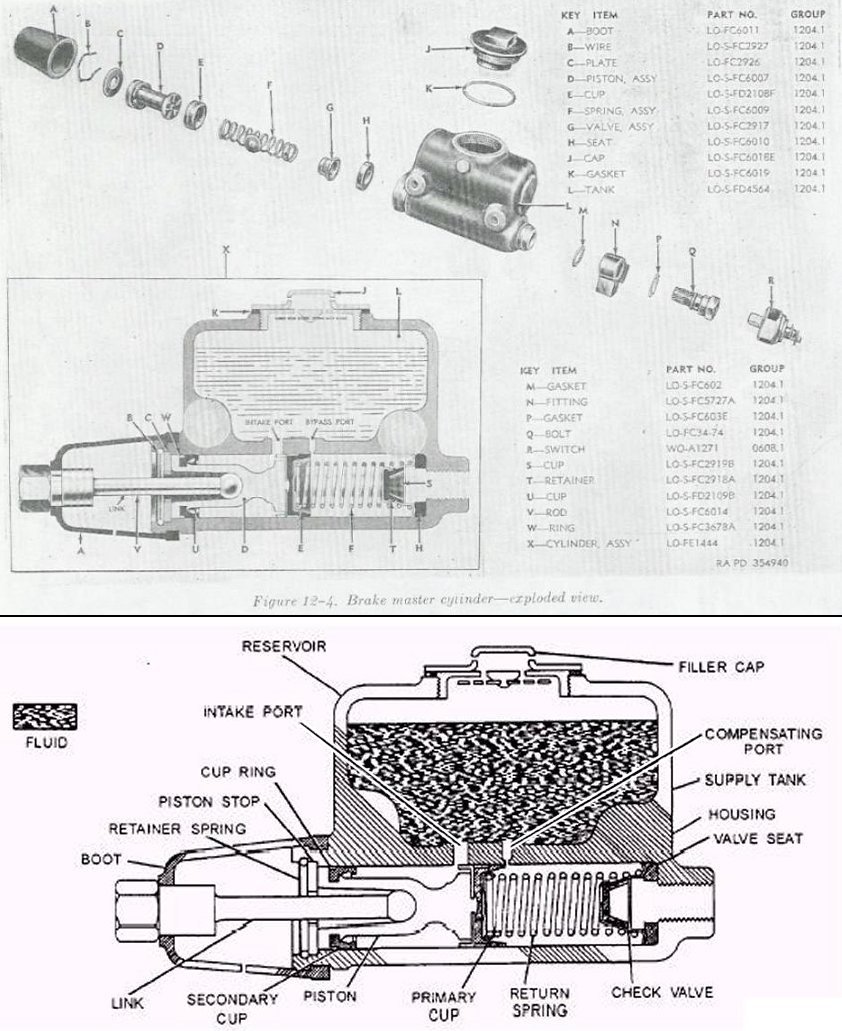
Jeep MB/GPW Foot Brake Major adjustments made simple [diagram 1]:
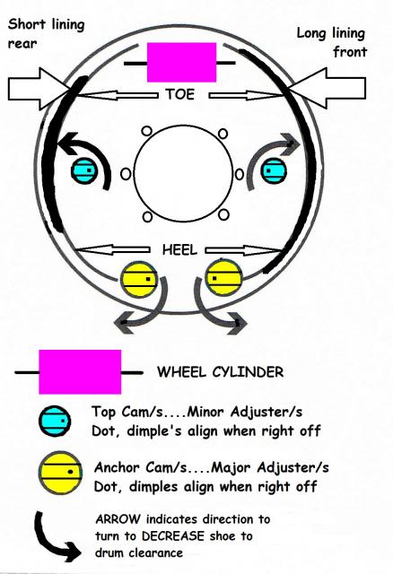
Brake shoes must be concentric with drums. This can’t happen with skimmed drums & standard shoes
[see diagram 2] 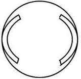
1. Turn all cam adjusters to fully retract all shoes
2. Turn all bottom anchor adjusters so dots [or arrows] face one another
3. Turn anchor in direction of arrow/s until the shoe heel/s drags on drum
4. Turn top cam/s in the arrow direction of the arrow/s to bring the shoe into contact with the drum.
This will cause the shoe/s heel/s to lose contact with the drum
5. Turn the anchors again in the direction of the arrows until the shoe heel/s just drag on the drum/s again
6. Repeat step #4
7. Repeat step #3 & #4 until cam adjustment no longer frees the shoe/s heel. Then tighten the anchor bolt nut/s
8. Repeat procedure for all shoes if you have not already done so
No table can cover all
know issues.If you have more to add, suggestions, comment please feel free
to do so by contacting the poster. Go to g503.com and PM User
Name artificer
|
Problem
|
Component Part |
Cause/Probable Remedy |
|
Brakes
drag all excessive drum heat maybe
lockup
|
Master Cylinder |
Insufficient free play adjust
actuating rod and check return spring fit
|
|
Brakes
drag all or some
|
All or any Hydraulic Cylinders
|
Mineral oil contamination |
|
Brakes
drag all or some
|
Wheel Cylinders |
Sticky/rusted/gummed hone or
replace
|
|
Brakes
drag all
|
Blocked Compensating or
Equalizing Port |
Either of above or dirt and
contaminants in reservoir
|
|
Brakes
drag all or some
|
Brake Shoes |
Improper adjustment Check and
adjust
|
|
Brakes
drag all
|
Brake shoes
Wheel & Master Cyl. |
Rusted up from lack of use. Major
overhaul |
|
Brakes grab & pull to one side |
Brake Shoe/s, Linings |
Oil/brake fluid/return spring/
adjustment
|
|
Brakes grab & pull to one side |
Brake Linings |
Different materials on same axle
|
|
Brakes grab & pull to one side
|
Brake Linings |
Leading &
trailing shoes reversed on one wheel
|
|
Brakes grab & pull to one side |
“U”
bolts, wheel bearing/s loose |
Check and re-tension |
|
Brakes grab & pull to one side |
Brake Drums |
Machined, scored or worn
differently. Repair - replace
|
|
Brakes grab & pull to one side |
Tyres or Wheel alignment |
Check pressures and tyre wear |
|
Pedal hard poor
brakes
|
Linings
|
Glazed. Sand paper or emery lining and
drum
|
|
Pedal hard poor
brakes
|
Lining/s |
Oil soaked. Replace in pairs |
|
Pedal
travel too far
|
M/C push rod or spacer
missing
|
Adjust free travel check and
replace spacer
|
|
Pedal
travel too far (hard)
|
Brake drum/s |
Worn scored out of shape. Check
machine or replace in pairs
|
|
Pedal
travel too far (hard)
|
Brake shoes |
Pump fast, comes up and hard.
Adjust
|
|
Pedal
travel too far (soft)
|
M/C, W/C, Hoses or Steel Lines,
Flaring and Fittings
|
Air in system. Find and repair
leak/s replace damaged parts. Adjust and bleed |
|
Pedal
travel too far (soft)
|
Linings
|
Loose rivets, replace linings
(pairs) or re-rivet
|
|
Pedal
pulsates (usually hard) on application |
Drum/s |
Out of round, oval. Check,
machine or replace (pairs)
|
|
Brake Squeal
|
Drums/linings |
Ingress of dirt and dust. Clean
|
|
Brake Squeal
|
Linings
|
Loose, glazed. Remedies listed above |
 The handbrake adjustment
is not difficult, and this type of park brake system is very effective if
properly adjusted.
One thing to be aware of
is that many people have played with your vehicle before you and there is
no guarantee everything is it's proper place, or, is to specifications and
some bits may be missing
altogether.
The handbrake adjustment
is not difficult, and this type of park brake system is very effective if
properly adjusted.
One thing to be aware of
is that many people have played with your vehicle before you and there is
no guarantee everything is it's proper place, or, is to specifications and
some bits may be missing
altogether.
1. Check the operation of
the the handbrake lever and pawl locking mechanism. Note:- When applying
the handbrake always turn the handle 1/4 turn (the same you do when
releasing) then turn back to lock when application is complete. This will
save Pawl wear & tear.
2. Establish that all
cable attachments are in place, tight, and that the outer cable is firmly
secured at the fire wall and other extremity.
3. Lubricate between the
inner and outer cables, ensuring free easy movement. ( This lube should be
done as an ongoing service
basis)
4. Disconnect the cable at
the Drum end. This ensures the cams(4 of) etc. are all in the off
position.
5. Check the brake band is
in place correctly, correct springs and all hardware
attached.
6. Elongated or oval holes
and worn clevis pins (4 & 5) and such may need components and holes
built up, re-drilled and pins
replaced.
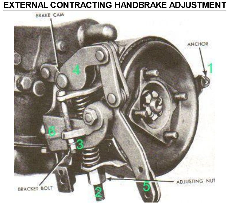
7. Anchor (1) is your
first point to adjust and there are two things of importance. Clearance
between the transmission lug to band attachment should be no more than
0.005". If larger, remove the band and adjust the gap by squeezing in a
vice, gentle persuasion or other suitable method. When fitted there is
between 0.005" and 0.010" drum to lining at that anchor. Lock wire must
not be overly tightened or
binding.
8. Adjust Nut (2) until
the Lining just binds with the
Drum.
9. Adjust Screw (3) until
the head engages on the Band and the Nut and Locknut are just snug against
the Bracket (6) Clearance should be around 0.010" when this
happens.
10. Back off Number 2 Nut,
two full turns, or give the Lining approximately 0.010" and the Drum
should turn freely.
11. Re-attach the cable,
and if it doesn't match up properly, the outer cable positioning needs
altering so everything lines
up.
12. The original MB/GPW
cable was not adjustable, but by now, modifications done so that it
can be.
13. This brake is meant
for parking and should not be applied when the vehicle is in motion unless
in an emergency situation.
14. The faster you go the
harder they wrap on.
15. Regardless of what
some may think, they are very efficient and serious damage may occur, I
have struck a tail shaft that looks like a corkscrew, so be
aware.
If you don't have any
hassles, it should take less than 20 minutes to obtain the best
results.
John
Gibbins.